
NetCDF-family files configuration
In this sections two simple examples of configuration of a NetCDF and a Grib file are presented.
NetCDF
NetCDF file description
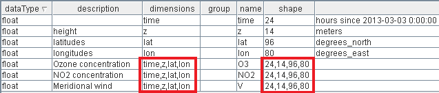
The following NetCDF file is part of the Polyphemus dataset already described. More specifically, this file contains 3 layers called NO2, V, O3. Each one of these 3 layers internally have elevation (called z) and time as additional dimensions.
From an abstract point of view, these layers can be seen as 2-dimensional arrays of 2D slices, where each array is composed by T x E slices where
- T = number of temporal positions.
- E = number of elevation positions.
Here you can find how the file is structured:
Note
Note that the z-dimension will be referred as elevation in the next steps.
The GeoServer internal reader is able to parse the NetCDF file and configure the 3 different layers taking into account their additional dimensions. With the following example, we are going to understand how to access these layers.
Configuring a NetCDF file
Go to
Stores->Add new Store. Then click on the NetCDF label: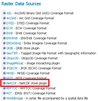
Enter
testNetCDFfor the Data Source Name field and$TRAINING_ROOT/data/user_data/multidim/polyphemus/polyphemus_20130303.nc( or%TRAINING_ROOT%/data/user_data/multidim/polyphemus/polyphemus_20130303.ncon Windows, remind to use / in file selector ) for the URL field. Then press Save.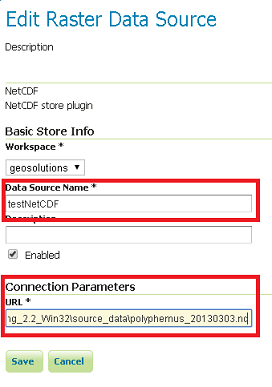
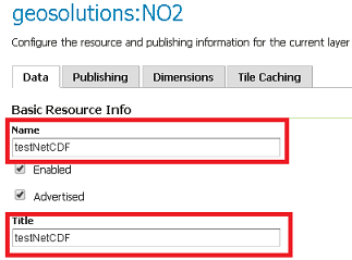
Click on the Publish button of the first layer called NO2
Then in the Layer configuration page you can see various parameters associated to the selected layer. Rename the layer testNetCDF, in order to avoid errors in the next sections.
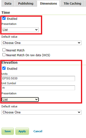
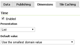
For configuring the time and elevation dimensions, you have to go to the Dimensions page and enable them. Also you should configure the Presentation as List in order to see these dimensions as separate values. The following settings allow to set specific time and elevation parameters for accessing a particular slice of the layer.
Click on Publishing tab, and assign the N02 style as the default style of the layer.
Click on Save, for saving the configuration.
Execute the following requests:
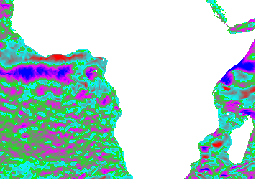
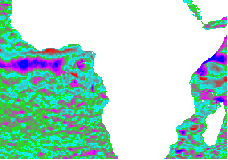
As you can see, the two images are different because they represents the same layer at two different time and elevation positions:
Request without parameters
Request with elevation=10 and time=2013-03-03T00:00:00.000Z
Grib
Grib File description
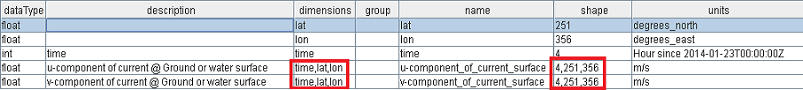
The Grib file we used in the following example contains information about the marine currents on the African coast. This file is composed by two layers:
- u-component_of_current_surface.
- v-component_of_current_surface.
It should be pointed out that the two layers contain an additional time dimension, so we can see the following file as a 3D array where the 3 dimensions are: latitude, longitude, time.
For a better comprehension, you can see the following screenshot of the image structure:
Note
All the Grib files used in the following training have been created by converting original WRF (Weather Research and Forecasting system) data in the Grib format.
Configuring a Grib File
The configuration of a Grib data is very similar to that of a NetCDF one. For this reason some steps will not be shown:
Go to
Stores->Add new Store. Then click on the GRIB entry: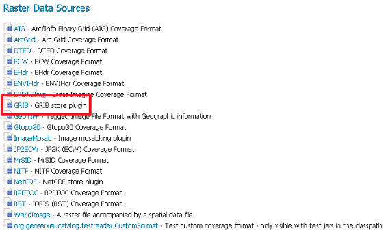
Enter
testGribfor the Data Source Name field and$TRAINING_ROOT/data/user_data/multidim/africa.grb2( or%TRAINING_ROOT%\data\user_data\multidim\africa.grb2) for the URL field.Click on the Publish button of the first layer called u-component_of_current_surface
Then in the Layer configuration page you can enable the additional parameters.
Click on Save, for saving the configuration.
Execute the following request:
http://localhost:8083/geoserver/geosolutions/wms?service=WMS&version=1.1.0&request=GetMap&layers=geosolutions:u-component_of_current_surface&styles=africa&bbox=339.9,-30.1,411.09,20.1&width=256&height=180&srs=EPSG:4326&format=image/png
http://localhost:8083/geoserver/geosolutions/wms?service=WMS&version=1.1.0&request=GetMap&layers=geosolutions:u-component_of_current_surface&styles=africa&bbox=339.9,-30.1,411.09,20.1&width=256&height=180&srs=EPSG:4326&format=image/png&time=2014-01-24T06:00:00.000Z
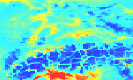
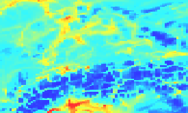
Compare the results:
Request without parameters
Request with time=2014-01-24T06:00:00.000Z
Note
The following requests have been rendered with a style called africa for highlighting the differences between the two images.